Can AI Write CAD for 3D Printing? Rendering Is Only the First Check
Published 2026-11-03

Ask an AI for a mounting plate and it can give you a plausible OpenSCAD file. Press Render, get an STL, and the task appears finished. A screw hole that stops halfway through the plate will not necessarily produce a render error.
Of 36 initial replies in the complete-coverage cohort, 30 rendered to STL. Of those rendered files, 21 passed the implemented checks and 9 failed at least one check. The cohort includes only deepseek-v4-flash and nemotron-3-ultra; partial groups are excluded. Error-driven repair raised the cohort's checked-pass count to 23. No physical parts were printed.
What the experiment actually covers
The six tasks were an open-top storage box, an M3 mounting plate, an L-shaped shelf bracket, a spur gear, a tube adapter and a raised-text name tag. Each prompt specified dimensions in millimetres. The prompts are included verbatim in the downloadable data.
These are code-generated parts, not image-to-3D meshes. OpenSCAD expresses solids and operations in code, so dimensions can be parameters you change. That makes the specification inspectable; it does not prevent a model from writing the wrong operation. For the other route, see what we found inside generated meshes.
We used retained replies from five API groups labelled deepseek-v4-flash, deepseek-v4-pro, gemini, gemma-4-31b and nemotron-3-ultra in the run records. A group label is not proof of its backend version; recorded returned versions and gaps are described below. The source was rendered with OpenSCAD 2021.01 and the STLs were checked with trimesh 5.1.0. This is not a comparison of the current versions of those products, and neither ChatGPT nor Claude was tested.
The raw output is published as JSON, produced
by scripts/measure-ai-cad.py.
Count the answers before counting the failures
A planned request is not a returned CAD file. A provider failure while asking for a repair also does not erase the code that arrived on the first attempt.
Scroll the table horizontally on smaller screens to compare all columns.
| Stage | Count | Meaning |
|---|---|---|
| Planned slots | 90 | Six prompts, three trials, five model groups |
| Saved initial replies and render outcomes | 71 | Includes render failures |
| Missing initial outcomes | 19 | 17 initial provider errors; 2 other unresolved slots |
| Recorded empty-reply re-asks | 9 | Events across collection, not extra parts or the number of still-missing outcomes |
| Complete-coverage cohort | 36 | deepseek-v4-flash, nemotron-3-ultra, all planned part/run pairs answered |
| Partial groups, answered slots | 35 | Pro 16, Gemini 9, Gemma 10; excluded from the cohort totals |
| Repair-stage provider errors | 1 | Recorded separately; the initial CAD failure remains an answered result |
The complete-coverage cohort contains only the two groups with a saved reply and initial render outcome for every planned part/run pair. The three partial groups remain in the raw data, but their successes are not pooled into the cohort totals. This avoids treating an unavailable API response as a malformed part or quietly improving the score by ignoring missing requests.
It does not remove selection bias. Complete coverage describes which slots were answered, not which models are best or how a fresh random sample would perform. Flash has six initial replies without a recorded returned version or request timestamp. Gemini’s partial group includes both gemini-3.6-flash and gemini-3.8-flash. Exact repair-model versions were not independently recorded.
A clean render can hide the wrong part
The mounting plate is the clearest example. Its outer dimensions matched the request. The sampled horizontal section at 2 mm above the base showed four openings with diameter and spacing within the implemented tolerance; absolute hole centring was not checked. The mesh was a single closed body. The holes still did not pass through the plate. Four openings in a horizontal section can be cavity openings; they do not establish four tunnels through the solid. This mesh had genus zero and failed the through-hole topology check.
Inspection of the retained code shows the centring mismatch precisely: the 4 mm plate spans Z = -2 to +2 mm, but the uncentred cutters start at -eps (-0.01 mm) and extend only in the positive Z direction. That leaves almost the lower half closed. This code inspection explains why a top view can suggest a finished mounting plate; the measured lower cross-section reveals the obstruction.
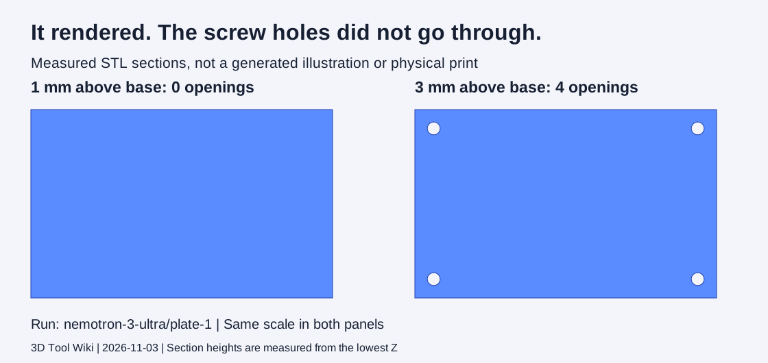
These sections are computed from the retained STL, not generated artwork or a physical-print photograph. The hero illustration is decorative. The plate run is nemotron-3-ultra/plate-1, shown in the examples table below.
Scroll the table horizontally on smaller screens to compare all columns.
| Run ID | Scope | Final bounds (mm) | Measured failure |
|---|---|---|---|
| deepseek-v4-pro/bracket-2 | Partial group, illustrative only | 50 x 40 x 4 | Code extrudes a planar XY L profile to 4 mm, rather than joining two shelf-support arms in perpendicular planes. |
| gemma-4-31b/box-1 | Partial group, illustrative only | 60 x 40 x 25 | A top-level solid cube unions with the hollow box, filling its cavity. |
| nemotron-3-ultra/plate-1 | Complete cohort | 80 x 50 x 4 | Holes that stop short of the far face. In every case here the plate was centred with center=true and the cutting cylinder was not, so it cut only the top half. |
The bracket and box examples come from partial groups, so they illustrate failure mechanisms without contributing to the complete-cohort totals. The bracket was a 4 mm extrusion of an L-shaped outline in the XY plane, instead of arms meeting in perpendicular planes with a gusset. Its through-hole topology check passed while its requested shape and bounds failed. The box included an extra top-level solid that filled its intended cavity. Both rendered successfully.
This is why checking only whether the model is watertight misses the decision that matters. A watertight object can be the wrong object. Our non-manifold explanation covers topology; the pre-print checklist adds dimensions and the intended solid or cavity.
What one error-driven repair changed
Only failed renders triggered a repair. The workflow sent the OpenSCAD error back once and rendered the new code. It did not send geometric measurements back when a part had already rendered successfully.
Scroll the table horizontally on smaller screens to compare all columns.
| Part | Initial replies | Initial pass | Final pass |
|---|---|---|---|
| Open-top box | 6 | 6 | 6 |
| Mounting plate | 6 | 5 | 5 |
| Shelf bracket | 6 | 3 | 3 |
| Spur gear | 6 | 0 | 2 |
| Tube adapter | 6 | 4 | 4 |
| Raised-text tag | 6 | 3 | 3 |
In this complete cohort, 6 initial renders failed. Error-driven repair produced 2 additional rendered meshes; both passed the implemented checks. Geometry failures in files that already rendered were not sent for repair.
The additional passes in the complete cohort came from deepseek-v4-flash/gear-1 and deepseek-v4-flash/gear-2. The first initially used module, an OpenSCAD keyword, as a parameter name. The second initially produced a mesh OpenSCAD could not close. Their repaired meshes passed our implemented size, bore, tooth-count and topology checks. We did not verify an involute tooth profile or test either gear against another gear.
A repaired render is useful, but this protocol has a blind spot: a plate with blind holes produces no error to paste back. The unchanged geometric failures do not show that an AI could never fix them. They show what this limited, error-driven repair procedure did and did not attempt.
Exactly what a pass means here
The general dimensional tolerance was 0.3 mm. Counts, such as teeth or holes, were checked as exact counts. A passing mesh had to be one watertight body and pass the implemented checks; incomplete measurements fail rather than silently passing.
| Part | Implemented checks | Important limits |
|---|---|---|
| Open-top box | Outer bounds, sampled cavity dimensions, floor-transition bracket and topology | Wall thickness is not checked at every location |
| Mounting plate | Bounds, sampled hole diameters and pitch, sampled hole count and genus-based through-hole topology | Correct topology does not certify absolute centring or mechanical fit |
| Shelf bracket | Overall dimensions compared irrespective of axis order, closed-body checks and genus-based through-hole topology | Arm thickness, hole diameter and placement, gusset and right angle are not fully checked |
| Spur gear | Bounds, tooth count, bore and topology | Tooth profile, pitch accuracy and mechanical meshing remain untested |
| Tube adapter | Diameter samples, sampled equivalent wall thickness, section lengths and through-opening | Equivalent diameters do not measure the minimum local wall of an irregular section |
| Name tag | Bounds, hole measurements, topology and raised geometry | Literal TEST text, font shape and independent plate/relief thicknesses are not verified |
The adapter’s section lengths are sampled in 0.5 mm steps, with a half-millimetre allowance for that sampling. Wall checks use 1 mm height intervals. Bed-contact area and downward-facing area are diagnostics, not pass/fail gates. We did not test support requirements, physical printability, strength or load-bearing use.
The full omissions remain attached to each run in unchecked_requirements. The benchmark’s headline counts must not be read as “every requested feature passed.”
A practical workflow for your next AI-written part
- Write a measurable specification. State outside dimensions, wall or floor thickness, hole diameter and spacing, and which openings must pass completely through. Distinguish a requested dimension from an assumption the model should ask about.
- Render and export the final mesh. In OpenSCAD, use Render (F6) and export the STL. For repeatable command-line rendering, the official OpenSCAD command-line documentation documents
openscad -o part.stl part.scad. Our retained runs used the 2021.01 executable; newer versions were not tested. - Measure the exported mesh. Confirm scale and bounds in the local STL viewer, then inspect the features that determine the job: a bore must be open through its depth; a box must have a cavity; separate solids must join where intended. The viewer’s general diagnostics do not replace dimension-specific CAD checks.
- Describe the failure precisely when asking for a revision. Send the render error when there is one. If the mesh renders but is wrong, state the observed mismatch, such as a hole that stops halfway through, and retain the original file for comparison. This geometry-feedback step is a recommendation, not a tested outcome in our error-only repair protocol.
- Inspect the sliced result and validate the intended use. Check perimeters, thin walls, cavities and how the part sits on the bed. Use the repair workflow for actual mesh defects. Repair cannot infer a missing design feature or prove a bracket can carry a load.
The wider AI model diagnostic guide follows the same principle: decide what the asset must do, then test that property. A successful export is evidence that a file exists, not that the design is finished.
Method and reproduction limits
The scripts retained replies, extracted code, rendered STLs and recorded failures. Requests used the prompts in the dataset without a system prompt. Provider output limits, retries and Gemini fallbacks were part of the collection process; this was not a controlled comparison of identical inference settings. The DeepSeek output cap was raised during collection after some replies ended without usable code. Missing or mixed version evidence remains disclosed rather than reconstructed from current aliases.
The November 3 measurement reads existing assets. No new CAD generation calls were needed to prepare this article. Cross-sections, bounds and topology are mesh-derived measurements; failure explanations are code inspection linked to those observations. Genus is used only for a single watertight body and does not prove that holes are positioned correctly or have the required diameter.
The downloadable JSON contains the prompts, model provenance fields where recorded, stage accounting, measurements, failure notes and unchecked requirements. Known version and timestamp gaps remain visible. It does not contain the full reply text, STL binaries or installed software. Those retained assets are local, and the private repository is not a public download. The published data supports checking the tables; reproducing generation would require new API calls and could return different versions and outputs.
No parts were physically printed. The defensible conclusion is narrower and more useful than a model ranking: rendering, geometric checks and physical validation are separate acceptance steps, and this dataset only measures the first two within the stated coverage.
Frequently asked questions
Can AI write CAD code for a 3D printable part?
It can produce OpenSCAD that renders to STL, but a rendered file can still have blind holes, a filled cavity or the wrong shape. Our retained sample separates rendering from implemented geometry checks. No physical prints were made, and a check pass does not certify every requested feature.
Did this test measure ChatGPT or Claude CAD performance?
No. The retained runs cover DeepSeek, Gemini, Gemma and Nemotron API groups. ChatGPT and Claude were not tested, and these results should not be attributed to them or used to rank current AI CAD products.
Does pasting an OpenSCAD error back into an AI fix the part?
It rescued some render failures in this sample. The protocol attempted one repair round after a render failure. It did not repair parts that rendered successfully but had incorrect geometry, so the improvement does not measure a full inspect-and-redesign workflow.
What should I check before printing AI-generated CAD?
Render and export the mesh, confirm real dimensions, inspect openings through their full depth, and check wall thickness, separate bodies and the slicer's layer preview. Verify fit and strength separately. Neither a clean render nor a watertight mesh proves the part will perform its intended job.