AI-Generated Model UVs: Check Them Before Repainting or Baking
Published 2026-11-09
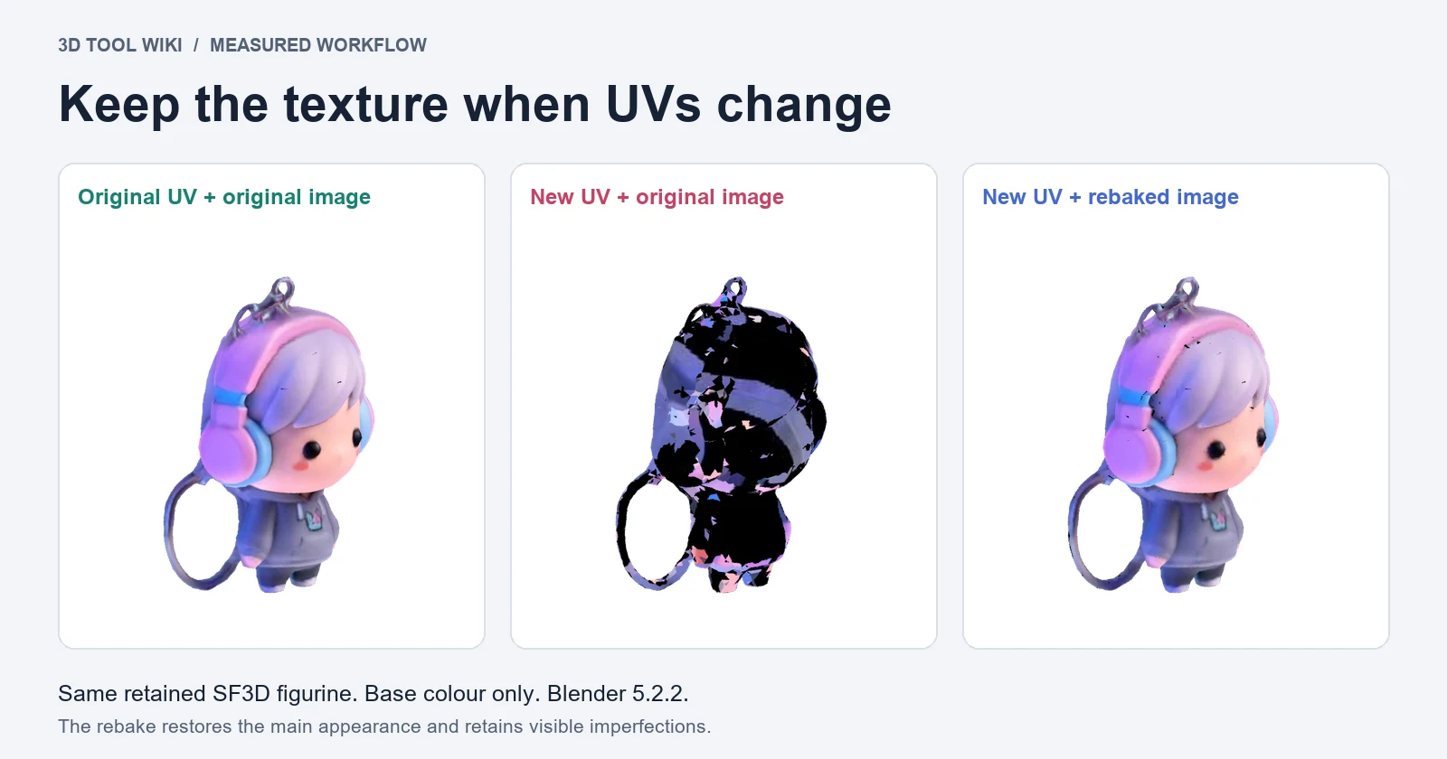
A generated GLB can look fine in a viewer and become a mess as soon as you move its UVs. The original image was made for the original layout. Changing where a face sits in that image changes the colour it receives.
We inspected eight retained textured downloads, then used one of them to test a complete base-colour transfer in Blender 5.2.2. The useful decision is which part of the current asset you need to preserve, and which part your next edit actually requires you to change.
What we found in eight retained GLBs
The files came from four input images, exported through Stable Fast 3D and TRELLIS.2 in September and October 2026. These are the textured subset of our generated-model baseline, inspected again on November 6. The results apply to those saved files and their recorded settings.
Every file had a UV map, and every UV corner was inside the 0 to 1 tile. Their edge-connected UV component counts nevertheless ranged from 372 to 4,369. A component here is a group of triangles joined across edges that share the same position, UV and material. The count includes tiny disconnected fragments; it should not be read as the number of deliberate artist-authored charts.
| Input | Retained export | Triangles | UV components* | Select Overlap faces* | Tiny or zero-area UV triangles* |
|---|---|---|---|---|---|
| charger | Stable Fast 3D | 25,660 | 372 | 0 | 0 |
| charger | TRELLIS.2 | 292,138 | 1,170 | 108 | 33 |
| figurine | Stable Fast 3D | 22,584 | 603 | 2 | 0 |
| figurine | TRELLIS.2 | 291,026 | 3,463 | 76 | 20 |
| mug | Stable Fast 3D | 32,104 | 609 | 19 | 0 |
| mug | TRELLIS.2 | 276,809 | 1,782 | 99 | 26 |
| pumpkin | Stable Fast 3D | 34,488 | 442 | 2 | 2 |
| pumpkin | TRELLIS.2 | 284,010 | 4,369 | 209 | 71 |
*A UV component joins triangles along an edge with identical positions, UVs and material index. Overlap is Blender's selected-face count, not overlapped area. The last column uses a UV-area threshold of 10−12. These are inspection readings, not pass/fail scores.
Blender’s Select Overlap marked faces in seven of these eight files. That tells us where to inspect. It does not tell us how much image area overlaps, whether the overlap was intentional, or whether a visible part of the intended edit will fail. The tiny-area column also uses a stated numerical threshold. A very small UV triangle can represent a very small surface feature.
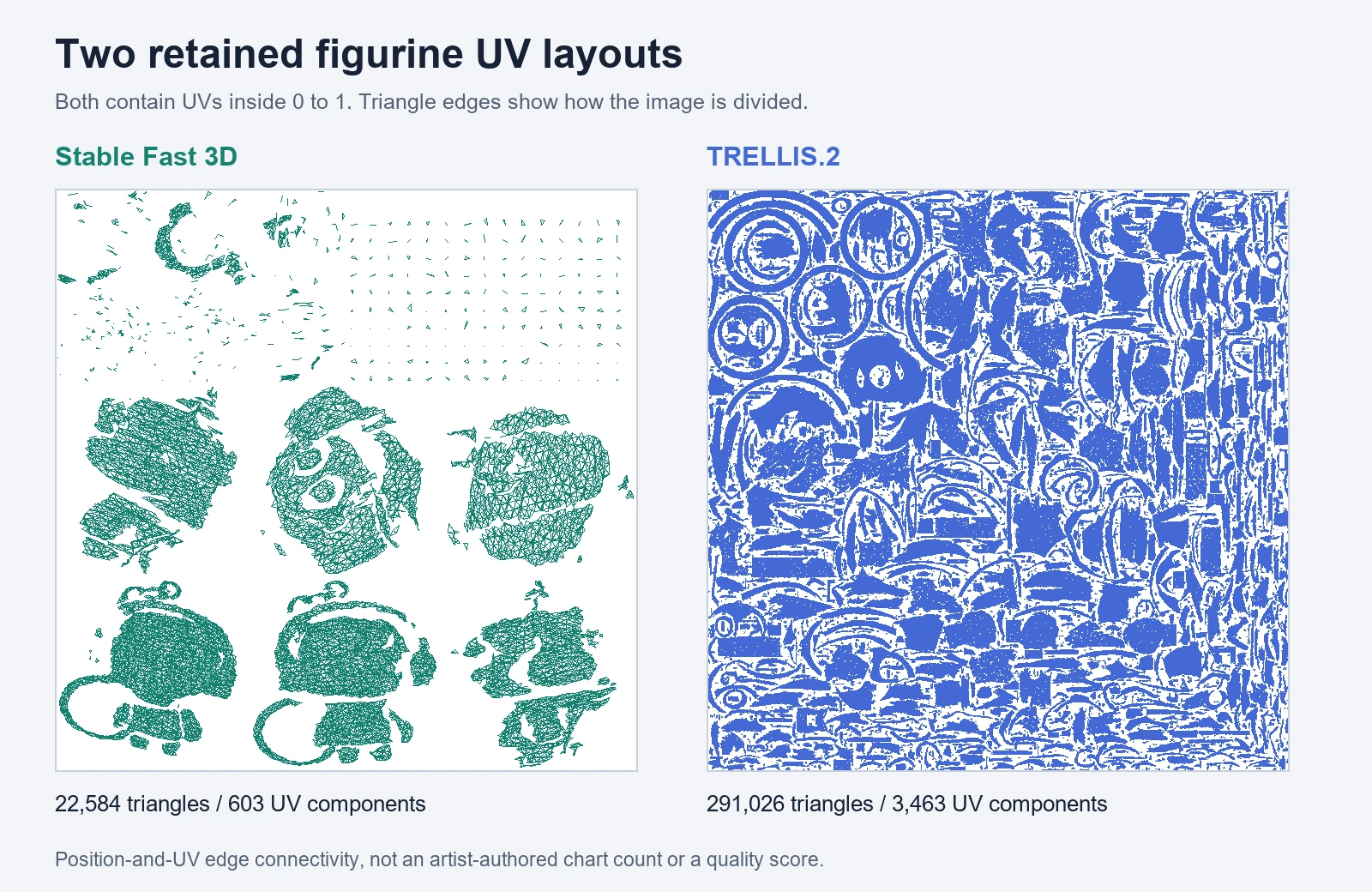
Plots from the files themselves. Neither fragmentation nor a Select Overlap flag is a generator quality score.
The practical consequence is to test the operation you intend to perform. A fragmented layout can already display its supplied texture successfully. It may still be inconvenient for painting a logo in a 2D image editor, allocating more pixels to a face, or baking onto a different mesh.
The raw output is published as JSON, produced
by scripts/measure-generated-uvs.py.
Check which coordinates the material actually uses
Start with a saved copy in Blender. Import the file through File > Import > glTF 2.0, select the mesh, and inspect Object Data Properties > UV Maps. Then open its material in the Shader Editor. A UV Map node can explicitly name a layer, so changing the selected layer in the list may leave that material reading another one.
Switch to the UV Editing workspace, enter Edit Mode and select the faces you want to inspect. An empty editor can mean that the relevant faces are not selected or that the wrong object is active. Check those conditions before deciding that the file has no UVs. In the material, distinguish an Image Texture from a Color Attribute or procedural setup. They require different preparation for image-based painting and export. Our GLB guide explains where those pieces live in the file.
For a diagnostic copy, create a new image with Generated Type set to UV Grid or Color Grid and connect it through an Image Texture node to the material’s base colour. Feed its Vector input from a UV Map node naming the layer being inspected. View the mesh in Material Preview and rotate around it.
Look for stretched cells, abrupt changes in their size, and seams through places where you want continuous detail. An even grid is a useful visual check, but it cannot tell you whether a different target resolution or an engine’s smaller mip levels will keep neighbouring islands separate. Blender documents the grid image types and UV display controls in its image and UV editor manuals. Blender Image Settings, Blender UV overlays
Use overlap as a location to inspect
In the UV Editor, use Select > Select All by Trait > Overlap in Blender 5.2. Keep UV selection sync disabled if you want to inspect the UV selection independently of the mesh selection. Blender selects overlapping UV faces, and its result should be checked on the corresponding surface. Blender Selecting UVs
If painting a mark on one surface changes another surface you wanted to keep independent, shared image space is a problem for that edit. A mirrored part intentionally sharing the same colour may work as designed. Likewise, coordinates outside one tile can belong to a repeating material or a multi-tile setup. Confirm what the material and destination expect before moving those coordinates into a single square. Blender UDIM workflow
Choose what needs to change
| Your next task | Start with | Check before committing |
|---|---|---|
| Use the supplied appearance on a static prop | Keep the existing layout | Inspect the visible surfaces in the destination application |
| Paint a specific mark or repair a seam | Try the edit on a copy of the existing layout | Check for shared pixels and whether the important area has enough resolution |
| Rearrange islands for easier painting | Add another UV map and transfer the appearance | Preserve the original map and image until the new pair is verified |
| Reduce or rebuild the mesh for deformation | Plan the target geometry and its UVs together | Test projection, topology and deformation separately |
Changing the UV layout leaves the mesh’s triangle structure in place. If the actual problem is dense geometry, intersecting parts or deformation around a joint, the next decision belongs to retopology. Repacking texture coordinates cannot solve those geometry problems.
Re-unwrap while preserving the original base colour
This is the same-mesh workflow we ran on the retained SF3D figurine. It transfers the base-colour image using Emission, avoiding the addition of scene lighting and reflections during the bake. Any lighting already painted into the original image remains. The comparison below uses that same simple emission material for every render.
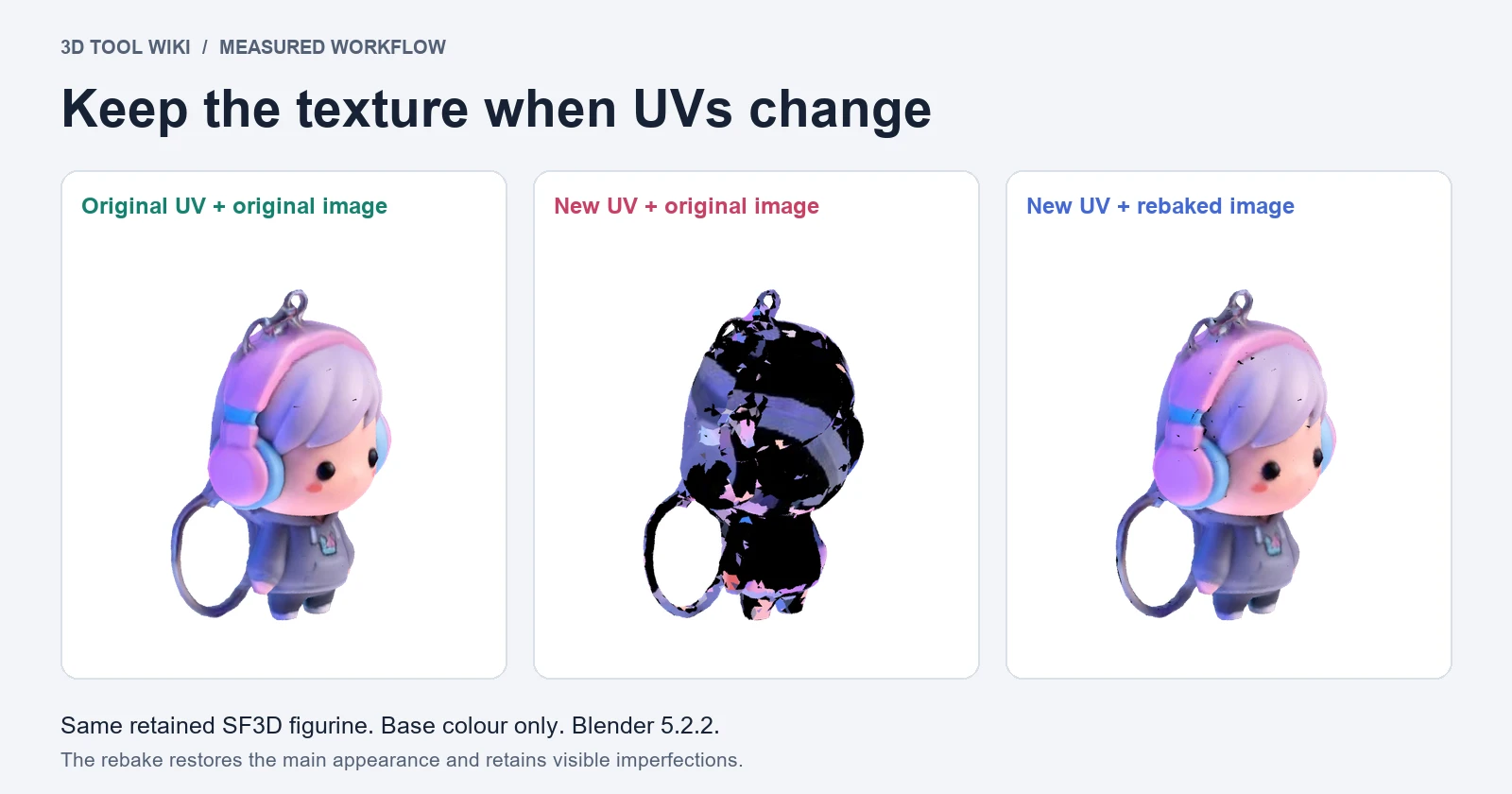
Only the UV/image pairing changes. The new layout with the old image scrambles the appearance. The rebaked image restores the main features, with small defects still visible.
1. Preserve the source and add a destination
Save a separate working .blend file and keep the original image. In Object Data Properties > UV Maps, rename the existing layer OriginalUV. Add another layer named RepaintUV.
Select RepaintUV before unwrapping. For the demonstration we selected all faces and ran UV > Smart UV Project with a 66-degree angle limit and an island-margin parameter of 0.02, leaving the other operator settings at their Blender 5.2.2 defaults. Those are the recorded demonstration settings. Use a layout suited to the surfaces and details you intend to paint, then check it with the grid.
2. Make the source texture read OriginalUV explicitly
Build a temporary material with the following connection chain.
UV Map (OriginalUV) > Image Texture (original image) > Emission > Material Output
The UV Map output goes to the image node’s Vector input, and the image’s Color output goes to the Emission Color input. The source appearance now has an explicit coordinate source while the mesh has another layout selected for baking.
Create a separate blank image for the destination. Our example used 1024 × 1024, matching the source image. Add another Image Texture node using this blank image. Leave that target node unconnected and select it last so it is the active node in the material. Blender bakes to the active Image Texture node. For a mesh with several materials, each relevant material needs its own correctly configured active target. Our example has one mesh and one material. Blender Render Baking
3. Bake into RepaintUV
Set the render engine to Cycles. In the UV Maps list, make RepaintUV the selected layer and the active render layer, using its camera icon. In Render Properties > Bake, choose Emit. Leave Selected to Active disabled for this same-mesh transfer.
We baked with an 8-pixel margin and the Extend margin type. Margin is a separate pixel setting from the Smart UV Project island-margin parameter. Check the result at the intended output size and viewing distance; this demonstration does not establish that eight pixels will suit another atlas or its mipmaps. Blender describes the margin modes and their role around baked islands in the baking manual. Blender Render Baking
Click Bake. When it finishes, save the destination image through Image > Save As in the Image Editor. Saving a .blend file alone should not be used as evidence that an external image has been saved.
4. Switch both the image and the UV source
For the check material, point the UV Map node at RepaintUV and replace the source image with the new baked image. Inspect the result against the saved original from several angles, especially fine lines and seams. Preserve the original pair until the new pair has passed those checks.
For a lit final material, connect the new image’s Color output to the original Principled BSDF’s Base Color input and make that image read RepaintUV explicitly. Keep any other original image channels on their original mappings until you have transferred and checked each one. The temporary Emission material is the base-colour diagnostic used for this comparison.
Our render recovered the figurine’s main colours and facial features. Small marks and seam defects remain visible. It demonstrates a working transfer path on that file, with the recorded resolution and settings. It does not establish lossless conversion or a better layout for every painting task.
If the bake is black, scrambled or leaking at the seams
| Symptom | Check first |
|---|---|
| Nothing was written into the intended image | Confirm the new Image Texture node is active in each relevant material and that the correct UV layer is the destination |
| The new image contains misplaced patches | Confirm the source texture is still explicitly reading OriginalUV |
| A circular-dependency warning appears | Use separate source and destination images, and keep the target image out of the source shader’s read path |
| Lighting or reflections appear in the base colour | Check the bake type and temporary shader, or use a correctly configured colour-only Diffuse bake |
| Neighbouring colours leak across seams | Inspect island spacing, bake margin and the texture resolution actually used in the destination |
| A bake between different meshes misses surfaces | Check source/target selection, projection distance and cage settings for that separate Selected to Active workflow |
The same-mesh example above needs neither a projection cage nor a selected high-poly source object. Moving to a different target mesh introduces those additional decisions. Use the procedure for the operation you are performing. Blender’s baking manual distinguishes Selected to Active and its ray/cage controls. Blender Render Baking
After a successful local check, test the asset through the real export and import route. GLB to FBX can change which material channels reach a reader, and our Blender to Godot test shows how much the route can matter. Keeping the new base-colour pair correct in Blender is one part of that journey.
Method and limits
We used Blender 5.2.2 LTS. The audit imports eight original GLBs and reads their UV layers, triangle coordinates and material boundaries. The connectivity calculation joins triangles across an edge only when both endpoints have identical local positions and UVs, within the same material. A shared point alone does not connect two components. Tiny disconnected triangles are included in the count.
Five synthetic controls test separated islands, deliberately stacked UV triangles, a collapsed UV triangle, coordinates outside the first tile, and an edge whose vertices are stored separately but have matching positions and UVs. The deliberately stacked case verifies Blender’s selected-face observation independently of the component calculation. Source-file SHA-256 hashes are recorded and checked again after inspection.
The transfer example uses one retained SF3D figurine. Its geometry remains unchanged while a second UV layer is unwrapped. We render the original mapping, the new mapping reading the old image, and the new mapping reading the rebaked image with the same camera and base-colour emission shader. The figure labels each render with its tested UV/image pairing.
The author works for the company behind Neural4D. The cohort here consists of the retained textured SF3D and TRELLIS.2 files from the earlier baseline. Its provenance, dates and exclusions remain in the downloadable data.
We have not measured minimum island padding, distortion across the surfaces, mipmap bleeding, other seeds, other export versions, rigging or overall game readiness. The transfer example does not validate normal-map transfer or projection to a retopologized mesh. For a model intended for printing, start with geometry and slicing checks, which answer a different downstream requirement.
The raw output is published as JSON, produced
by scripts/measure-generated-uvs.py.
Frequently asked questions
Why does my AI-generated model look textured but have difficult UVs?
Its existing texture can fit a layout that is awkward to edit. Many small islands, unintended overlaps, distortion or insufficient spacing can make new painting or baking harder. In our eight retained GLBs, every file had UVs inside the 0 to 1 tile, while the edge-connected UV component count ranged from 372 to 4,369. The count describes fragmentation and does not decide whether a particular edit will work.
Can I re-unwrap an AI-generated model without losing its texture?
Yes. Keep the original UV map and source image, create another UV map, and bake the existing appearance into a new image for that new layout. In our Blender 5.2.2 example, an explicit UV Map node kept the source image reading OriginalUV, while RepaintUV was selected as the destination and the new Image Texture node was active. We tested the base-colour image through an Emission bake.
Do UV coordinates outside 0 to 1 always mean the model is broken?
No. Repeating textures and multi-tile workflows can use coordinates outside that tile. Judge the coordinates against the intended material and destination application. A single unique texture atlas and a tiled material have different requirements.
Why did my texture become scrambled after Smart UV Project?
The new coordinates point to different parts of the existing image. Preserve the old UV map before unwrapping, then transfer the appearance to a new image. Simply changing the layout and continuing to read the old image reproduced that failure on our retained SF3D figurine.
Does this workflow also transfer normal maps and make the mesh animation-ready?
Our demonstration transfers one base-colour image on the same mesh. Tangent-space normal maps need a workflow that accounts for the changed tangent basis, and animation suitability also depends on geometry, topology and deformation. Those checks require separate tests.