How to Check a Model You Did Not Make, and Why the Order Matters
Published 2026-09-17

Advice about checking a downloaded model usually arrives as an unordered list: make sure it is watertight, look for non-manifold edges, check the scale, count the shells. Do all of them and you will probably be fine.
The order is not incidental, though, and we can show why with a single measurement. Repair settings are distances. A distance only means something relative to the size of the thing it is applied to, and size is exactly what a downloaded file is least reliable about.
The measurement behind the order
One mesh: a sphere that should be 100 mm across, exported to STL, with coordinate noise a millionth of its size, which is the ordinary condition of a file that has been through a conversion. One setting: merge vertices closer than 0.1 mm, a reasonable choice for a part this size and the value that recovers this mesh correctly.
The only thing that changes between the three rows is a uniform scale factor, the kind a unit mix-up produces.
| Apparent size | Tolerance as share of model | Vertices | Boundary edges | Shells | Zero-area faces | Watertight |
|---|---|---|---|---|---|---|
| 100 mm, correct | 0.001 | 2,562 | 0 | 1 | 0 | yes |
| 0.1 mm, read 1000× too small | 1.0 | 7 | 0 | 5,120 | 5,120 | no |
| 100 m, read 1000× too large | 0.000001 | 14,581 | 15,358 | 5,119 | 0 | no |
The middle row is the one worth sitting with. The tolerance is not slightly too large, it is the entire width of the model, so every vertex is within merging distance of every other vertex. All 5,120 faces survive as entries in the file and every one of them has zero area. The mesh is gone, and nothing about the operation reported an error.
The bottom row fails in the opposite direction and is less dangerous only because it is obvious: at 100 m the tolerance is a millionth of the model, nothing merges, and the file stays the triangle soup it was.
Why a unit mix-up produces exactly a factor of 1000 is a separate story, told in why a 3D model imports at the wrong size. The short version is that four of the five common mesh formats do not record a unit at all.
The order, and what each step is actually for
1. Size and units
Read the bounding box in millimetres and compare it against what the object is in the real world. A phone case is about 150 mm; if the longest edge reads 0.15 the file was authored in metres, and if it reads 5.9 someone worked in inches.
Do this before touching anything else, because every setting after this point is a distance.
2. Parts and loose shells
Count the separate shells before counting holes. A model can be one closed object, or an assembly of several, or one object plus debris floating inside it where you cannot see it. These need different responses, and the hole count means something different in each case.
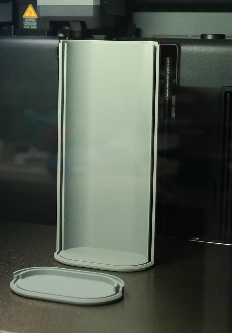
A shell count of two is not a defect here. The box and its base were authored as separate parts and print as two objects, so a report saying “2 shells” is describing the design. The same reading on a figurine that should be one piece means something has come apart, and on a scan it usually means debris. The number alone does not tell you which, which is why this step comes before the hole count rather than alongside it.
This is also where a conversion shows its cost: parts that were named and separate in the source arrive as one anonymous object in an STL, as measured in what GLB to STL conversion throws away.
3. Topology
Now watertightness, boundary edges, non-manifold edges and winding consistency are worth reading, because the model is the right size and you know how many things it contains.
One caution carries over from what “same vertex” means in an STL: a topology reading for an STL is partly a property of the tool, not only of the file. Two tools that reconstruct shared corners differently will hand you different numbers, and both can be right. If a report says every triangle is its own shell, that is the signature of a strict reader on a noisy file rather than a shattered model.
Sealing holes does not necessarily clear a non-manifold error, which has its own longer explanation in non-manifold edges.
4. Appearance, only if the destination needs it
UVs, materials and vertex colours matter for a renderer or a colour printer and are irrelevant to a single colour FDM print. Check them last, because deciding they are missing is only useful once you know the geometry is worth keeping.
How to tell a repair worked
Record four numbers before and after any repair pass: face count, vertex count, bounding box, and the topology readout. Then apply three rules.
A large drop in vertex count is a warning, not a win. Merging duplicate corners on our test mesh took 15,360 stored vertices down to 2,562, which is correct. Taking it to 7 is not tidying, it is collapse.
Face count should not change during a merge. In all three rows above it stayed at 5,120, including the row where the model was destroyed. Face count staying constant while area goes to zero is the specific signature of over-merging.
The bounding box should be unchanged. A repair that moves the outside of the model has done something other than repair.
If the numbers do not survive those three rules, the setting was wrong for the model rather than the model being unfixable. Go back to step 1.
When nothing works
Sometimes there is no correct setting. If the coordinate noise in a file is within an order of magnitude of its smallest real feature, the tolerance that would join the duplicates is also large enough to destroy detail, and the window closes. That case is measured in what “same vertex” means in an STL: at 0.01 mm noise on a model whose shortest edge was 3.46 mm, no tolerance tested recovered the mesh.
At that point the fix is upstream rather than in a repair tool: re-export from the source at higher precision, or ask for a format that records the connections instead of leaving them to be guessed.
Our STL viewer and GLB viewer report size, shells, boundary edges and watertightness on upload, in that order, for the reason this article is about. Everything happens in the browser and no file is uploaded anywhere.
Method
One icosphere at subdivision level 4, scaled to 100 mm, exported to STL and reloaded with processing disabled so that no merging was applied on load. Gaussian coordinate noise was then added at one millionth of the model’s longest edge, seeded for reproducibility, and the result was scaled by 1000 and by 1/1000 to produce the two mis-read cases. Because the mesh is scaled after the noise is added, the noise scales with it, so the three rows differ only by a uniform factor. A single fixed merge tolerance of 0.1 mm was then applied to all three. Measured with trimesh 5.1.0 and numpy 2.5.2 on 8 September 2026.
Not measured here: what any named repair tool uses as its own default, which its documentation states rather than requiring a test.
Full results, method and limitations: Why a model's scale has to be checked before any repair tolerance is applied.
The raw output is published as JSON, produced
by scripts/measure-check-order.py.
Frequently asked questions
What should I check first in a downloaded 3D model?
The size, before anything else. Repair settings are distances, so they only mean something once the model is at the size it is supposed to be. We ran one mesh through a fixed 0.1 mm merge tolerance at three apparent scales. At true size it came out watertight and correct. Read a thousand times too small, the same setting crushed all 5,120 faces onto 7 points. Read a thousand times too large, it did nothing at all.
Why did repairing my STL make it worse?
Most often because the model was not at the size the setting assumed. A merge distance is an absolute number, and if it is a large fraction of the whole model it collapses real geometry instead of joining duplicate corners. In our test, a tolerance that was one thousandth of the model at true size became the entire width of the model when that model was imported at a thousandth of its intended size, and every face in it ended up with zero area.
How do I know if a repair actually worked?
Do not judge it by the hole count alone. In our destroyed case the mesh reported zero boundary edges, which reads like a clean result, while every one of its 5,120 faces had collapsed to zero area. Check that the face count, the vertex count and the bounding box are still what they should be, and treat a sudden drop in vertex count as a warning rather than as tidying up.
In what order should I check a 3D model before printing?
Size and units first, then how many separate parts and loose shells there are, then topology such as watertightness, holes and non-manifold edges, then appearance such as UVs and materials if the destination needs them. Each step depends on the one before it: topology settings are distances that need a correct size, and a hole count is meaningless until you know whether the loose pieces are real parts or debris.
Does a model that looks fine in a viewer need checking?
Yes, because the failures that matter are mostly invisible. A model imported at the wrong scale renders perfectly, just small or large, and a viewer will helpfully frame it to fill the window either way. Loose internal shells, non-manifold edges and inconsistent winding all render as a normal looking surface. The bounding box in millimetres and a topology readout tell you things the picture cannot.