How to Repair a Broken STL File: Holes, Non-Manifold Edges and Flipped Normals
Published 2026-07-16

You slice a model and the preview looks wrong, or the slicer refuses outright with a “non-manifold” or “not watertight” warning. Almost every 3D printing session eventually meets a broken STL. The fix usually takes minutes once you can name the defect.
Why STL files break in the first place
An STL stores nothing but a bag of triangles. There is no notion of a solid, no thickness, no guarantee that the triangles even join up. Whether the result is printable depends entirely on how those triangles were produced, and there are four common sources, each with its own failure habits:
- Modeled by hand in a mesh tool, where boolean operations and mirrored geometry leave internal walls and coincident faces.
- Downloaded from a marketplace, where a model built to look good in renders was never checked for print integrity.
- 3D scanned or photogrammetry captured, which produces holes wherever the camera could not see and noise around thin features.
- AI generated from a photo or text prompt, which introduces a specific set of topology problems covered later in this article.
The point is that “broken” is not one thing. Before you can fix an STL, you need to know which of its problems is the one your slicer is complaining about.
The five errors that actually stop a print
Most failures reduce to five defects. Learn to name them and the repair becomes obvious.

- Holes (not watertight). The surface has a gap, so there is no closed volume. The slicer cannot tell the inside from the outside.
- Non-manifold edges. An edge is shared by more than two faces, or two shells meet at a single point. This geometry cannot exist as a real solid.
- Flipped normals. Some triangles face inward. Rendering may hide this, but the slicer reads those regions as inside-out and carves holes or inverts walls.
- Duplicate and degenerate faces. Overlapping triangles and zero area “sliver” triangles that add no shape but confuse the volume calculation.
- Isolated shells and floating debris. Small disconnected fragments, stray triangles or internal ghost objects that the slicer tries, and fails, to interpret.
Diagnose before you touch anything
Repairing blind is how you turn one problem into three. Spend two minutes finding the actual defect first.
- Read the slicer’s own report. PrusaSlicer, Cura and Bambu Studio all flag non-manifold edges and open surfaces on import, and often tell you how many. That count is your progress bar.
- Look at the raw mesh. Load the file in a viewer and orbit around it. Missing walls, see-through patches and obvious floating bits show up immediately. You can do this without installing anything in our free online STL viewer, which opens the file locally in your browser with no upload.
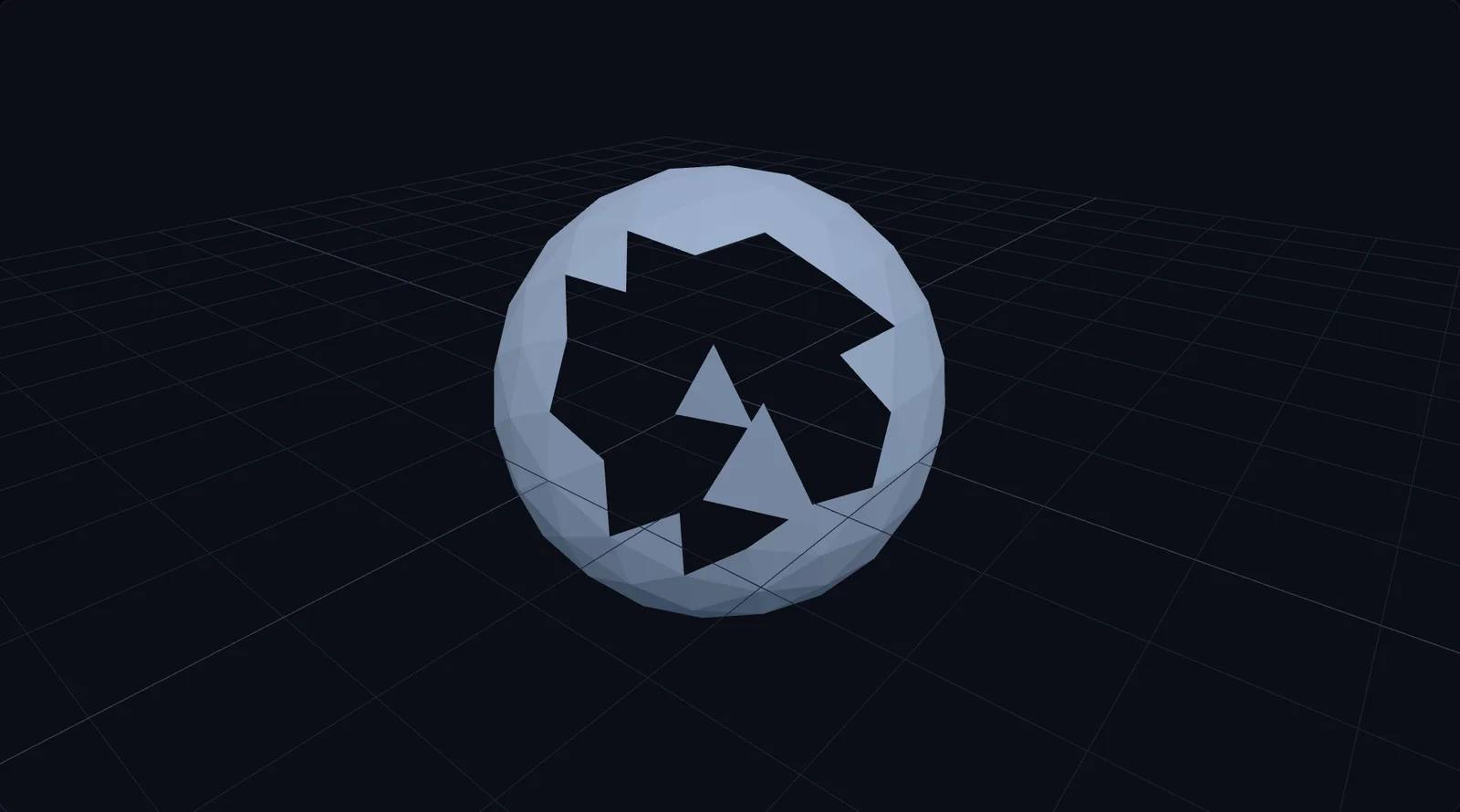
A deliberately broken test STL in our own viewer. The missing faces read as a see-through hole (the surface has no thickness), and the two floating shards near the gap are isolated debris a slicer would choke on. Screenshot: 3D Tool Wiki.
- Check, do not assume. A model can render perfectly and still be full of internal faces and flipped normals. If a print keeps failing for no visible reason, run a dedicated analysis pass rather than trusting the preview.
- Separate the two defects the report tends to conflate. Holes and non-manifold geometry are different failures with different fixes, which is why sealing every hole sometimes changes nothing at all. Non-manifold edges explains what that count is actually counting and when you can print the model regardless.
Which repair tool should you use?
All the mainstream options are free except Netfabb. The honest summary: start automatic, escalate to manual only when the automatic result is distorted or rejected.
| Tool | Cost | Type | Best for |
|---|---|---|---|
| Slicer built-in fix (PrusaSlicer, Cura) | Free | Automatic | The zero effort first attempt |
| Windows 3D Builder | Free | Automatic | One-click repair of most everyday breakage |
| Browser repair tools | Free | Automatic | Quick fixes with nothing installed |
| Autodesk Netfabb | Paid | Automatic + manual | Badly damaged files, production use |
| MeshLab | Free | Manual | Full control when auto-repair distorts the shape |
| Blender 3D-Print Toolbox | Free | Semi-automatic | People who already work in Blender |
Path 1: automatic repair, try this first
For the majority of everyday breakage, an automatic repair is all you need, and it is worth trying before you open anything more technical.
Your options, from least to most effort:
In PrusaSlicer (Windows): import the STL as usual. If the mesh is damaged, an orange warning triangle appears next to the object’s name in the right panel. Right-click the model (or the warning icon itself) and choose Fix through the Netfabb. PrusaSlicer hands the mesh to the Windows repair service and swaps in the fixed version; the triangle disappears when it succeeds. This option only exists on Windows 10 and 11.
In Windows 3D Builder: on Windows 11 install it free from the Microsoft Store first (it is preinstalled on Windows 10). Open your STL and click Import model. If the mesh is broken, 3D Builder outlines it and shows a banner in the corner: “One or more objects are invalidly defined. Click here to repair.” Click the banner, wait for the outline to turn clean, then use File, Save as and pick STL as the format (it defaults to 3MF).
Other automatic options:
- Autodesk Netfabb. The long-standing specialist for print preparation, with more aggressive automatic repair and control over how holes are bridged. Overkill for a simple gap, ideal for a badly damaged file.
- Browser based repair tools. A wave of free online fixers will close holes, weld duplicate vertices and re-orient normals in the browser. Convenient for a quick pass, though for confidential or large files a local tool keeps everything on your machine.
Automatic repair is fast, but it is a black box: it decides how to close a hole for you, and on a complex or organic shape that guess can be wrong. When the result distorts detail you care about, move to manual control.
Path 2: manual repair in MeshLab
When auto-repair mangles the geometry or simply gives up, MeshLab is the free tool most people reach for. It exposes the individual cleaning operations as separate filters, so you fix exactly what is wrong and nothing else.
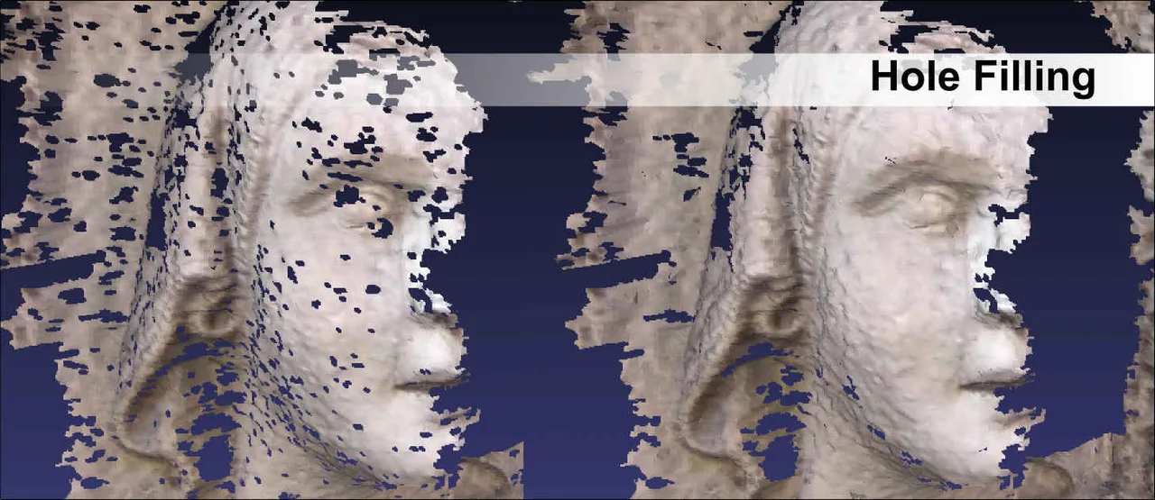
Hole filling on a scanned mesh in MeshLab, part of its cleaning and healing filter set. Image: MeshLab, meshlab.net.
Import your STL with File, Import Mesh, then work through this order of operations. The exact menu paths matter, because the repair filters are spread across three different submenus:
- Clear vertex clutter. Run
Filters > Cleaning and Repairing > Remove Duplicate Vertices, thenRemove Unreferenced Verticesfrom the same submenu. This alone often resolves phantom errors, because exported meshes routinely contain thousands of coincident vertices. - Delete junk faces. Still under
Cleaning and Repairing, runRemove Zero Area FacesandRemove Duplicate Facesto eliminate the sliver triangles that break volume calculations. - Fix non-manifold geometry. Run
Filters > Cleaning and Repairing > Repair non Manifold Edges. If MeshLab reports remaining problems, follow up withRepair non Manifold Vertices by splitting. - Remove floating debris. Run
Filters > Cleaning and Repairing > Remove Isolated pieces (wrt Diameter)and start with the default 10 percent diameter: anything smaller than a tenth of the model is deleted as a stray fragment. - Close the holes. This one lives elsewhere:
Filters > Remeshing, Simplification and Reconstruction > Close Holes. Set “Max size to be closed” conservatively (the default is 30 edges), apply, then raise it gradually if gaps remain. Small increments stop the filter from capping openings your design actually needs. - Fix flipped normals. Run
Filters > Normals, Curvatures and Orientation > Re-Orient All Faces Coherently. Note that this only works once the mesh is manifold, which is why it comes after step 3, not before.
To check your progress at any point, run Filters > Quality Measure and Computations > Compute Topological Measures and read the log panel: it reports boundary edges (holes) and non-manifold edges directly. When both reach zero, export with File, Export Mesh As and choose STL.
If you are new to the interface, this walkthrough of the cleaning and remeshing filters covers the exact menu items above:

Why AI generated meshes are the worst offenders
Here is the part that surprises people. I work in the image-to-3d generation industry, and the meshes these tools produce are, as a class, the messiest input a repair workflow sees. That is not a knock on the tools, it is a direct consequence of how they build geometry. (Our About page explains that background and the disclosure that comes with it.)
Almost every modern image-to-3d system, including the ones covered on this site, does not model a surface the way a person would. It generates an implicit representation of the shape, essentially a 3D field describing where the object’s surface lies, and then extracts a triangle mesh from that field with an algorithm called marching cubes. Tencent’s Hunyuan3D pipeline, for example, denoises a latent, decodes it into a signed distance field, and only at the final step converts it into an explicit mesh by marching cubes.
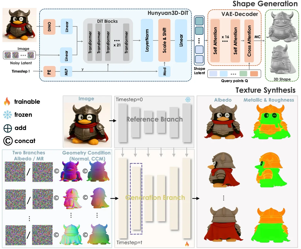
The two-stage Hunyuan3D 2.1 pipeline: shape generation first, texturing second. The triangle mesh itself is only extracted at the end of the shape stage, which is where the topology problems are born. Source: Tencent Hunyuan3D (GitHub).
That extraction step has consequences you will feel at the repair bench:
- Dense, uneven triangulation. Marching cubes tiles the surface on a grid, so you get far more triangles than the shape needs, unevenly distributed. Great for capturing detail, heavy to print and slow to edit.
- Topological noise. Any noise in the underlying field becomes tiny disconnected shells and floating fragments away from the main body.
- Non-manifold pinch points. Thin walls and self-touching regions, where two surfaces come close, frequently extract as non-manifold edges.
So the repair recipe for an AI mesh is different from a scanned or modeled one. Do not start by closing holes. Start by removing isolated pieces to strip the debris, then decimate to bring the triangle count down to something sane. In MeshLab that is Filters > Remeshing, Simplification and Reconstruction > Simplification: Quadric Edge Collapse Decimation: set “Percentage reduction” to 0.5 for a first pass (half the triangles), and tick Preserve Boundary of the Mesh, Preserve Normal and Preserve Topology so the simplification does not create new defects while it works. Only then repair non-manifold edges and close whatever holes remain. Clean up the density and the noise first, and the classic watertight repair becomes trivial.
A repair workflow you can reuse
Put together, the whole process is a short decision tree:
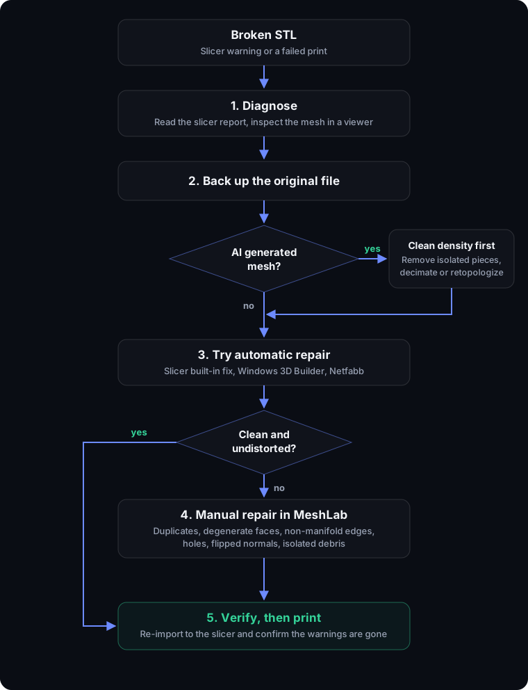
- Diagnose. Read the slicer report and eyeball the mesh in a viewer. Note whether it is holes, non-manifold geometry, normals or debris.
- Back up. Copy the source file before changing anything.
- Try automatic repair. Slicer fix, 3D Builder or Netfabb. If the result is clean and undistorted, you are finished.
- For AI meshes, clean density first. Remove isolated pieces, then decimate or retopologize before any hole filling.
- Escalate to MeshLab for manual, filter-by-filter control when automatic repair distorts the shape or fails.
- Verify. Re-import to the slicer and confirm the warnings are gone before you commit to a multi-hour print.
None of these steps is difficult on its own. The skill is reading the mesh correctly at step one, because a broken STL is never just “broken.” It is holes, or non-manifold edges, or flipped normals, and once you can name the defect, the fix is only a filter away.
Two things sit either side of this workflow. Step four, cleaning density before repairing, is a decimation decision, and how far each method moves the surface is measured rather than guessed. And when the mesh is dense enough that repair keeps failing, the answer is usually not a better filter but rebuilding the topology outright.
Frequently asked questions
What does a non-manifold error actually mean?
A non-manifold mesh contains geometry that could not exist as a real solid object, most often an edge shared by more than two faces, or two parts of the surface touching at a single vertex. A slicer cannot decide which side is inside and which is outside, so the print fails or produces artifacts.
Can I repair an STL file without installing any software?
Yes. Windows 3D Builder is built in and repairs most files in two clicks, and several browser based repair tools close holes and fix normals without an upload to a server. For stubborn meshes, or when you need control over what gets changed, a desktop tool like MeshLab is more reliable.
Will repairing an STL bring back detail that is missing?
No. Repair makes a mesh watertight and printable, but it cannot invent geometry that was never captured. Hole filling spans a gap with new flat or smoothed triangles, which is an approximation, not the original surface. Always keep the source file so you can re-export if a better fix becomes possible.
Why does my STL look fine on screen but still fail to slice?
Rendering only needs the outer surface to look right. Slicing needs a mathematically closed volume. Flipped normals, internal walls, duplicate vertices and zero area faces are often invisible in a viewer yet still confuse the slicer. Run a dedicated check rather than trusting the preview.
Are AI generated 3D models harder to repair than modeled ones?
They tend to need more cleanup. Most image-to-3d systems extract their mesh from an implicit field with marching cubes, which produces dense, uneven triangulation and stray disconnected shells. The fix is usually to delete isolated pieces, retopologize or decimate, and only then close the remaining holes.
Does converting an STL to another format repair it?
Not by itself. A format conversion re-encodes the same geometry, so holes and non-manifold edges travel with it. Some tools run a light cleanup pass during import or export, but that is a side effect, not a dependable repair step.