STEP vs STL: Converting Both Ways, and Why One Direction Barely Works
Published 2026-08-11

Someone asked you for a STEP file and all you have is an STL. There are dozens of converters promising exactly that, so this looks like a five minute problem. It is not, and the reason is worth understanding before you send anything to a machine shop.
What is the actual difference between STEP and STL?
The usual answer is “STEP is parametric, STL is a mesh”, which is true and not much use. The difference that matters is what each file says about a curve.
STEP, standardised as ISO 10303, stores geometry as mathematical surfaces. A hole is a cylinder: an axis, a radius, a height. STL stores a list of triangle corners. A hole in an STL is a ring of flat facets that looks round from a distance.
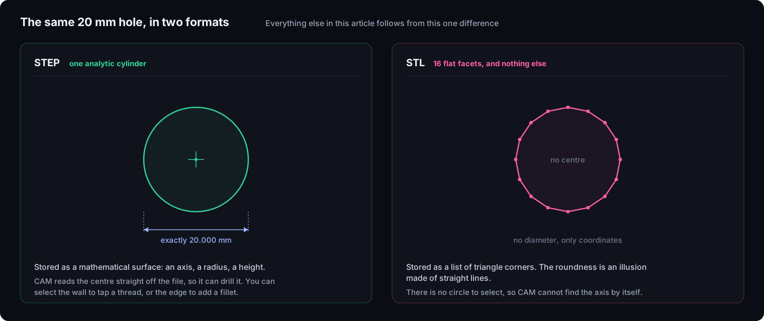
Every practical difference falls out of that one distinction. Because STEP knows the hole is a cylinder, CAM software can read its centre and drill it, and you can select its wall to tap a thread. Because STL only has coordinates, there is no centre to find and nothing to select. Xometry puts the limitation plainly: STL data contains no information on curves, so any curve, radius or circle is a series of lines and planes (Xometry).
Two more things travel in a STEP file and not in an STL, and both cause real damage when they go missing:
- Units. An STL is unitless. An edge of length “10” might be 10 mm, 10 inches or 10 metres, and the importing software guesses. STEP declares the unit in the file.
- Assembly structure. Export a 50 part gearbox as STL and it becomes one fused lump of intersecting triangles. STEP preserves the nested tree, so a manufacturer can isolate each component.
How do I convert a STEP file to STL?
This direction is easy, and there are two reasonable routes.
Export from CAD. Every CAD package has an STL export, with settings variously called tessellation, deviation, chord height or resolution. This is the one setting that matters: it controls how finely the mathematical surface is chopped into triangles. Too coarse and your cylinder arrives visibly faceted, and no downstream tool can restore it.
Let the slicer do it. PrusaSlicer, Bambu Studio and OrcaSlicer all import STEP directly. Bambu Studio exposes linear deflection and angle deflection settings that control the same thing, where smaller values mean a denser mesh and slower imports (Bambu Lab wiki). This route is usually better, for a reason covered further down.
Can I convert an STL to a STEP file?
You can produce a file with a .step extension. You will not get a CAD model, and the difference between those two statements is the whole problem.
An automatic converter does not look at your mesh and recognise that sixteen facets used to be a cylinder. It maps one flat B-rep face onto every single triangle. Recognising free form surfaces from an arbitrary set of triangles is, as CAD Exchanger’s engineers put it, practically impossible and computationally non-deterministic (CAD Exchanger).
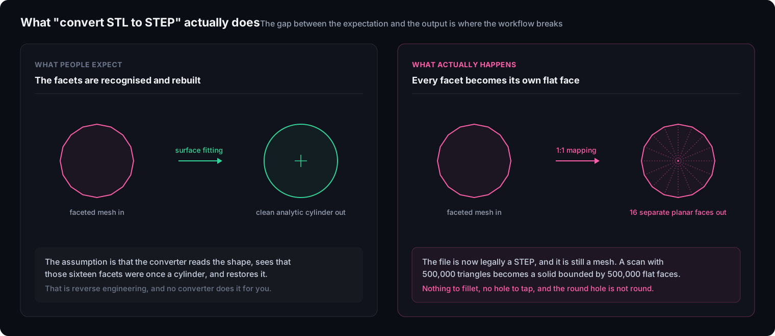
So a scan with 500,000 triangles becomes a solid bounded by 500,000 planar faces. It is watertight. It opens in SolidWorks. And it is useless for the operations people convert it for, because filleting an edge needs a continuous curve and your continuous curve is now hundreds of discrete segments.
The tools that do this all hit the same wall, but they hit it in different places:
| Tool | What you get | The limit that bites |
|---|---|---|
| FreeCAD (Create Shape from Mesh, then Refine Shape) | Watertight faceted solid | Refine merges coplanar triangles on flat areas, so flat faces come out clean. Curved surfaces stay faceted. |
| Fusion 360 (Mesh to BRep) | Watertight faceted solid | Under 10,000 facets converts normally. Between 10,000 and 49,999 it warns about performance but proceeds. At 50,000 or more it errors out and blocks the operation (Autodesk). |
| SolidWorks ScanTo3D | Patchwork NURBS surfaces | The closest thing to real surfacing here, but users report meshes importing invisibly and Mesh Prep Wizard buttons greyed out. A long standing workaround is to convert the STL to OBJ in MeshLab first. |
| Online converters | Faceted solid | Wrap the mesh as-is, and time out entirely on high vertex counts. |
Why does the shop keep asking for STEP?
Because their software cannot quote or machine your part without it, and this is a hard constraint rather than a preference.
Automated quoting platforms enforce it explicitly. Protolabs limits STL files to its 3D printing services, so a machined or moulded part needs STEP or IGES. Fictiv accepts meshes for 3D printing but requires proper solid bodies for CNC and injection moulding. Xometry treats STL as a validation and communication format for additive manufacturing, and recommends staying in STEP as long as possible for precision work (Xometry).
The mechanism behind the policy is worth understanding, because it explains why no amount of file conversion fixes it. To drill a hole, CAM software selects the cylinder wall and computes the axis and depth from it. Given a mesh, there is no cylinder wall, only hundreds of angled triangles, so the machinist has to find the centre manually and force the toolpath. Worse, surface milling a faceted model does exactly what you asked: the machine cuts thousands of microscopic flat planes into the metal, reproducing your low resolution triangles in steel, wrecking the finish and inflating cycle time as the tool stutters through every facet.
Which is why an STL sent for a machined part usually produces one of three responses: the job is declined, the shop asks for a STEP file, or the quote arrives with hours of engineering labour priced in.
Do slicers really slice STEP files?
They import them. None of them slice the mathematical surfaces, and the difference matters more than it sounds.
When you drop a STEP into PrusaSlicer or Bambu Studio, the slicer uses the OpenCASCADE CAD kernel to convert it into a dense triangle mesh in the background, then slices that mesh. The original STEP is not preserved. So “native STEP support” does not mean B-rep slicing, it means the triangulation now happens inside the slicer instead of inside your CAD export dialog.
That relocation is the actual benefit, and it is a real one. The slicer can pick a tessellation fine enough to recognise true curves, then emit G2 and G3 arc moves in the G-code rather than hundreds of tiny straight segments. At speed, a low resolution STL makes a printer stutter through micro segments; an arc command keeps the motion smooth and the machine quiet.
What if I actually need an editable model?
Then you need reverse engineering, and it is worth naming that honestly rather than hunting for a better converter. There are two routes.
Manual remodelling. Import the mesh, lock it as a visual reference, and build a new CAD model over the top: planes aligned to its flat regions, true circles sketched over its faceted holes, features extruded to match. The output is clean, lightweight and fully parametric, because it encodes design intent rather than scan noise. It is also the slower route.
Automated surfacing. Specialist software drapes a quilt of NURBS patches over the mesh. Much faster, and the result carries no design intent: a hole that was meant to be exactly 10.00 mm comes back as a slightly wavy patch measuring 9.98 in one direction and 10.02 in another, faithfully reproducing the noise in your scan.
The economics follow from that. Practitioners in the 3D scanning community report roughly USD 30 to 90 per hour to clean a raw scan into a usable watertight mesh, and USD 100 to 250 per hour when the deliverable is a genuinely parametric STEP model, depending on complexity and location. On the software side, Geomagic Design X is the industry standard and priced for service bureaus; QuickSurface sits in the mid market at around EUR 1,700 per year for the Pro tier.
.stp vs .step, and the protocol trap underneath
Two naming issues catch people out, and one of them silently destroys information.
.stp and .step are the same format. There is no difference whatsoever. The three letter version is a leftover from DOS and early Windows, which capped extensions at three characters. Rename one to the other and nothing changes.
The application protocol is the one that bites. STEP is modular, and your CAD tool asks you to pick a protocol on export, usually in a dropdown most people never think about:
| Protocol | Carries | The trap |
|---|---|---|
| AP203 | Geometry, topology, assembly structure | No colour data. Colour code an assembly so the machinist can tell the parts apart, export as AP203, and it arrives as a single grey block. |
| AP214 | Geometry plus colours, layers, basic design intent | The safe default when visual distinction between parts matters. |
| AP242 | Merges both, adds model based definition and semantic manufacturing information | The modern standard, encoding tolerances and GD&T into the model itself. Older CAM software can struggle to read the semantic data. |
If you have ever sent a carefully colour coded assembly and had the shop reply asking which part is which, this dropdown is why.
The short version
Going down, from STEP to STL, is a one way street you control. Set the tessellation deliberately, since nothing downstream can add back detail you did not export.
Going up, from STL to STEP, is not a conversion. Automatic tools produce faceted solids that satisfy a file extension requirement and fail every engineering operation. If the receiving end needs to machine or modify the part, budget for remodelling. What each route actually produces walks through the three of them, including the one that is worth the effort.
Keep the parametric file. Almost every painful STL to STEP story starts with the original CAD file being lost or never supplied. The mesh is an export, in the same way a JPEG is an export, and our guides on 3MF vs STL and what a GLB file is make the same point for the printing and real time worlds. If the mesh is all you have and it also needs repair before printing, our guide on fixing a broken STL covers that first.
You can check which tools in the directory read and write each of these formats on our format compatibility table.
Frequently asked questions
Can a STEP file be converted to STL?
Yes, and this direction is routine. Every CAD package exports STL, and PrusaSlicer, Bambu Studio and OrcaSlicer import STEP directly. The only decision that matters is tessellation quality: how finely the mathematical surfaces get chopped into triangles. Export too coarse and curves come out visibly faceted, which cannot be undone afterwards.
Can I convert an STL to a STEP file?
You can produce a file with a .step extension, but not a usable CAD model. Automatic converters map one flat face to every triangle in the mesh, so a 500,000 triangle scan becomes a solid bounded by 500,000 planar faces. It opens in CAD and it is watertight, but there is no cylinder to select for a thread and no continuous edge to fillet. Xometry describes the operation as a salvage and reconstruction exercise rather than a true conversion.
Is STEP better than STL?
For anything machined, modified or quoted, yes. STEP stores exact mathematical surfaces plus units, assembly structure and, depending on the protocol, colour. STL stores a bag of triangles with no units and no part hierarchy. For 3D printing specifically, STL is fine and remains the default, because a slicer has to triangulate the geometry anyway.
Why do people use STL instead of STEP for 3D printing?
Because slicing needs triangles in the end regardless, and STL is universally supported. Handing a slicer an STL means you controlled the tessellation yourself in the CAD export, which is more predictable than relying on the slicer's STEP import, and it avoids the geometry bugs that STEP import still occasionally hits.
What is the difference between .stp and .step?
Nothing. They are the same format. The three letter .stp extension is a leftover from DOS and early Windows, which limited extensions to three characters. Both open identically in every modern CAD tool, and renaming one to the other changes nothing about the file.
Do slicers actually slice STEP files?
No slicer slices the mathematical surfaces directly. PrusaSlicer, Bambu Studio and OrcaSlicer use the OpenCASCADE kernel to convert the STEP into a dense triangle mesh on import, then slice that mesh. The advantage is real but different from what most people assume: you move control of the tessellation from the CAD export dialog to the slicer, which can then fit smoother arcs into the G-code.
How much does it cost to get a real CAD model from a mesh?
It is priced as engineering labour, not as processing. Practitioners in the 3D scanning community report roughly USD 30 to 90 per hour for cleaning a scan into a watertight mesh, rising to about USD 100 to 250 per hour when the deliverable is a genuinely parametric, machinable STEP model. The dedicated software starts around EUR 1,700 a year and runs to tens of thousands for the industry standard package.